
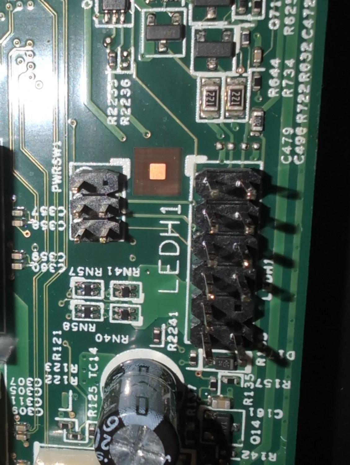
I’m using the motherboard from a Dell Inspiron 3847 for this build but I can’t figure out the front IO and I can’t find instructions for this motherboard anywhere. In the original case the front panel IO is handled by a single cable. Is what I’m trying to do hopeless? Surely there’s a way to connect this to my new case.
I’m seeing “PWRSW1” in the cluster to the left.
It is possible to deduce which header is the power switch.
Do you have a multimeter and do you know how to use it?
You want to start by figuring out which pins are GND. Ultimately, you’re looking for a 3.3V signal that is always on.
Connect your power button to a pair of pins that correspond to 3.3V and GND. Pressing the power button pulls that 3.3V signal low, which tells the embedded controller that it’s time to boot up.
If you still have the case, you can also use the connector to make the same determination. With a multimeter set to continuity mode and each probe connected to the right pin, pressing the power button will result in a ‘beep’
I don’t have a multimeter but I need one and I need to learn to use one. Is there one you recommend to noobs? In any case, I think I found an adapter that should solve my issue. Thank you!