Yes, but think about it like you’re a Chinese manufacturing engineer with only basic electronics education. You COULD do that design, build out the pcb, custom tool it to fit your plastic housing, etc etc… Or you could go to the manufacturer down the street who already makes pre designed voltage reg MCU’s on a board and spend like, 20 minutes in an IDE to code the specific voltage levels and button presses.
When production volume and turnaround time is the only things that matter in this shovel waste crap, “wasting” silicon is less expensive financially than building out the optimal solution.
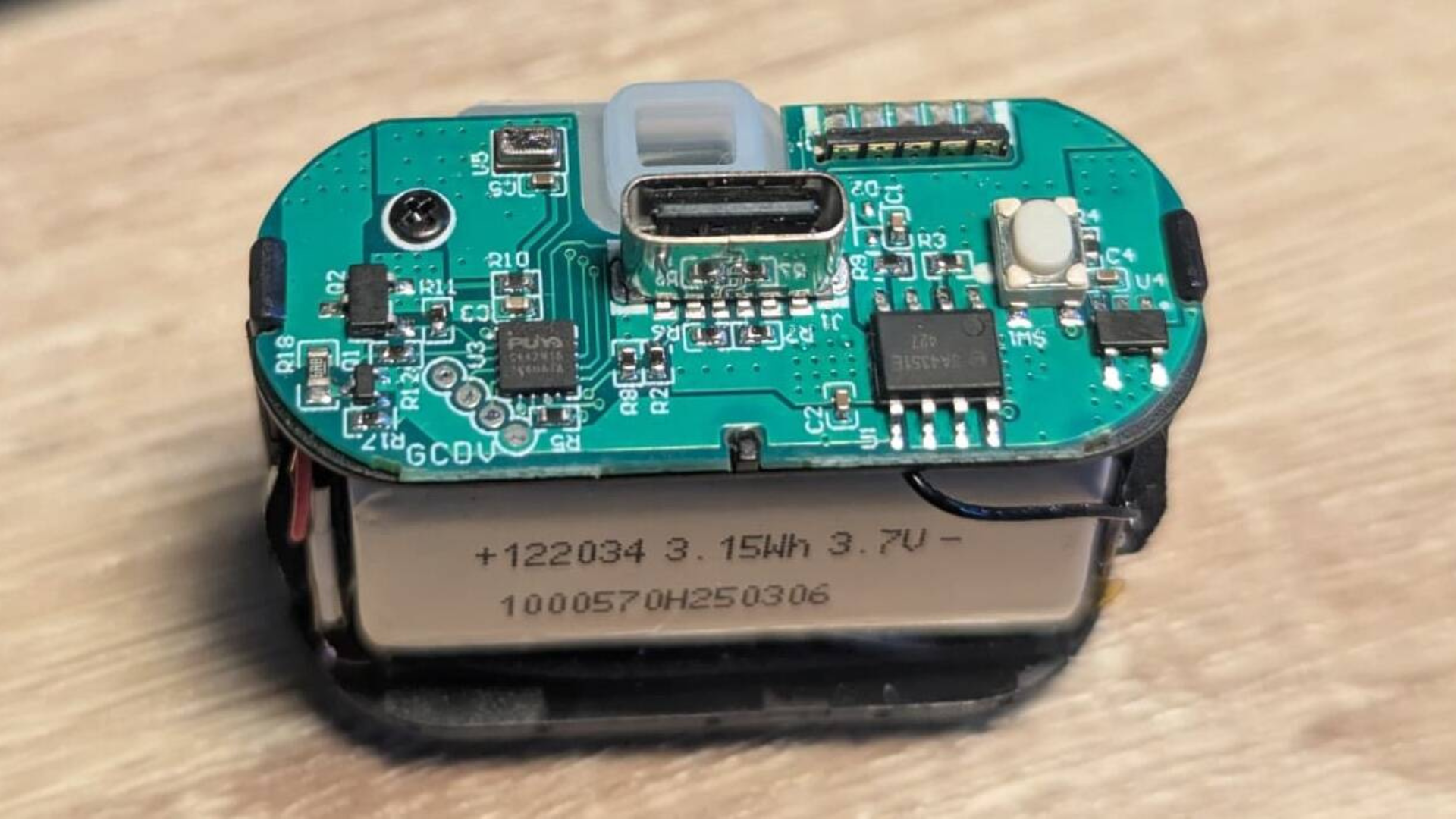
my guess would be it’s a parts commonality thing, it’s not hard to make it the old way, there are datasheets for it too. sure you could probably make tiny and cheaper (30x10mm? maybe smaller) analog board with two chips and mosfet working as pwm controller and current limiter, but it’ll have different passives for different battery sizes and heater powers. or you could make one design with optional usb port that you might just not solder on, and depending on model you just put different firmware inside
The old way is actually the analog style you’ve mentioned, but that was the very early days of ecigs well before they became mass market, the cottage industry modding scene had no hope of creating sophisticated microcontrollers and the charger wasn’t even USB, it was a DC jack & plug. Lavatube was the first time we had that kind of microcontroller regulation & then the DNA15 and DNA20 came out, got cloned by China and that changed the game forever.
The problem with the older way is consumers understand watts alone as a relatively consistent measurement of power much better than they would the relation between voltage, resistance & current draw. They didn’t want to learn Ohm 's Law back then and wouldn’t want to know about it now. Microcontrollers simplified that massively.
Designing a board to run a microcontroller like that is actually pretty simple.
I’ve done it for fun with a couple similar microcontrollers, and whilst I’m an EE by training I don’t do it professionally plus my training is from before embedded system, so I count as a Junior EE for that.
I’m pretty sure that even a freshly graduate Chinese EE can even on their own figure out the general recipe for integrating something this (following the datasheet, add crystal + load caps, plus about 1 caps each power pin for power filtering plus 1 global power filtering cap, plus possibly a pull-down/up resistor on the RESET pin) in a week or two and then for subsequent projects it will be feasible to do it in a few days.
Really, there’s other shit in there (say, battery management) that’s more work to figure out than how to add and place the parts for an entry level ARM microcontroller to work.

Yes, but think about it like you’re a Chinese manufacturing engineer with only basic electronics education. You COULD do that design, build out the pcb, custom tool it to fit your plastic housing, etc etc… Or you could go to the manufacturer down the street who already makes pre designed voltage reg MCU’s on a board and spend like, 20 minutes in an IDE to code the specific voltage levels and button presses.
When production volume and turnaround time is the only things that matter in this shovel waste crap, “wasting” silicon is less expensive financially than building out the optimal solution.
my guess would be it’s a parts commonality thing, it’s not hard to make it the old way, there are datasheets for it too. sure you could probably make tiny and cheaper (30x10mm? maybe smaller) analog board with two chips and mosfet working as pwm controller and current limiter, but it’ll have different passives for different battery sizes and heater powers. or you could make one design with optional usb port that you might just not solder on, and depending on model you just put different firmware inside
The old way is actually the analog style you’ve mentioned, but that was the very early days of ecigs well before they became mass market, the cottage industry modding scene had no hope of creating sophisticated microcontrollers and the charger wasn’t even USB, it was a DC jack & plug. Lavatube was the first time we had that kind of microcontroller regulation & then the DNA15 and DNA20 came out, got cloned by China and that changed the game forever.
The problem with the older way is consumers understand watts alone as a relatively consistent measurement of power much better than they would the relation between voltage, resistance & current draw. They didn’t want to learn Ohm 's Law back then and wouldn’t want to know about it now. Microcontrollers simplified that massively.
Designing a board to run a microcontroller like that is actually pretty simple.
I’ve done it for fun with a couple similar microcontrollers, and whilst I’m an EE by training I don’t do it professionally plus my training is from before embedded system, so I count as a Junior EE for that.
I’m pretty sure that even a freshly graduate Chinese EE can even on their own figure out the general recipe for integrating something this (following the datasheet, add crystal + load caps, plus about 1 caps each power pin for power filtering plus 1 global power filtering cap, plus possibly a pull-down/up resistor on the RESET pin) in a week or two and then for subsequent projects it will be feasible to do it in a few days.
Really, there’s other shit in there (say, battery management) that’s more work to figure out than how to add and place the parts for an entry level ARM microcontroller to work.