
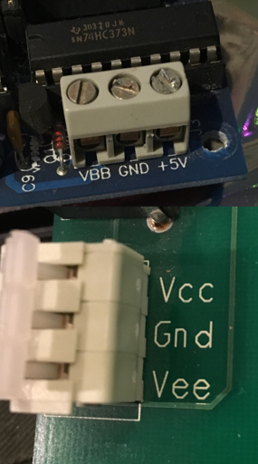
I am reading up on logic circuits, families and levels because it’s fun. I have no formal education in physics, computing or electronics.
For power supplies, sometimes one of the supply rails is referred to as ground (abbreviated “GND”) – positive and negative voltages are relative to the ground. In digital electronics, negative voltages are seldom present, and the ground nearly always is the lowest voltage level. In analog electronics (e.g. an audio power amplifier) the ground can be a voltage level between the most positive and most negative voltage level.
I know from previous reading, that electricity - at least when it comes to direct current, but perhaps even when it comes to AC? - has a way in (“line”?) and a way out (“neutral” or “ground”? - disregarding for a second the fact that ground also carries current in case of a ground fault).
Again, from previous reading, I know that we work computers by either supplying them voltage or not (or in some circuits a higher voltage and a lower voltage). In any case, it’s a choice between one or the other, since that is what we are trying to represent: boolean true or false.
So, what is this “negative voltage”? Is this a figure of speech or can voltage actually have a negative value? The part from the article that I quoted above states in relativistic terms, that “the ground can be a voltage level between the most positive and most negative voltage level” (italic text by me), which makes me assume “yes”. But if voltage is electromotive force, how can it be negative? I amusingly imagine a force “sucking” the current backwards. 🤭
Explain it to me as if I was five. 👶
Generally, my understanding, is there is a “flow” and a negative reading would be flowing the other direction. Thinking about a multimeter - it usually expects flow from red to black, but if you swap those around, you get a negative number as it flows from black to red.
The actual number is usually (not always) the important part - the potential difference between the two ends or something like that. That difference is going to behave similarly no matter which direction, but we assigned it numbers like that to make talking about voltages easier.
I think there’s a very physical but also intuitive way of thinking about this which eliminates all of the confusion (even with current conventions)
Forget about voltage and let me introduce potential Think about that as a landscape, its height changes and can be mapped in a height map. It corresponds to the „arbitrary energy level“ a particle on which a force may act. Imagine a ball on a curved hill: when ignoring friction and elasticity, the ball has contact with the plane at a singular point and will begin to roll down the hill. That’s what electrons do in a electric field (they rise to the top actually but you may think about current as „virtual“ positive particles which engineers do all the time. The „sea level“ is usually defined as 0V (the potential is also measured in volts)
Now the concept of voltage becomes nothing more than a height difference. In my opinion this beautifully explains concepts like Kirchhoffs voltage law: walk a circle on earths surface and measure your net height change… it’s always 0.
So to finally ( :D ) answer your question: a negative voltage is a negative height change. You just switch the terminals so that charge flows in the opposite direction.
Also current conventions become less confusing, because there is something all scientists and engineers can agree on: a voltage source creates a hill and a valley in its electric potential, the hill is + and the valley -, engineers think about current as virtual positive charge which will move from + to -, scientists will think about it as electrons moving from - to +.
walk a circle on earths surface and measure your net height change… it’s always 0. If you aren’t already, you should become a teacher 🤣🩷 Thanks!!!
May I just ask, what “virtual” means here? Non native speaker. 🙏
You’re welcome, I’m glad this explanation made sense, I’m also non-native :D
They are like places where electrons could be, you could also call them „electron holes“. If an electron flows through a conductor, it kicks off other electrons bound to atoms taking their place, which then become free electrons, it’s like a chain reaction without the amplification thing. But they aren’t „physical particles with a positive charge“
You could say electrons flow from left to right but you could also say that holes flow from right to left. You may hear an engineer or electrician say that electrons flow from + to -, because it’s just easier to communicate.
Most components like resistors don’t care about current direction anyway. But semiconductors like diodes do, they’ll heat up very quickly if connected in the wrong way.
For most household appliances this is completely irrelevant because the sine potential (and the current flow it causes) change directions every (depending on where you live) 10ms. Yes your phone is semiconductor based, but your phone charger rectifies the outlets AC current into a DC current with a defined direction.
Often times we use earth ground as the source of 0V. Can you end up with differences in potential on different “earth grounds”?
The lowest geographic place in the United States is Badwater Basin in Death Valley. It’s altitude is -282 feet. That’s a negative altitude.
What does that mean? It means that Badwater Basin is below the 0 altitude level, which we have chosen to define as “mean sea level.” We could have chosen a different altitude too be zero, but we didn’t.
If there is a pathway from the sea (at Mean Sea Level) to Badwater Basin, then the water will flow to the basin, because it would have a lower potential energy in the basin.
Voltage is potential difference. It is always the difference in potential between two different points. But like altitude, we often don’t say one of the two points out loud because it’s a common reference level.
A positive charge in a vacuum will gain speed (kinetic energy) moving from a higher potential to a lower potential, because its potential energy goes down. It doesn’t matter whether it’s going from +9V to +5V versus 0V to -4V. The change in potential is the same.
In simple terms, a Voltage is the difference in the electric potential between two points or in other words, a difference in how much electrons are attracted to one point by comparison to how much electrons are attracted to another (and, depending on said different, they will move in towards one of those points or not move at all is the difference is 0)
So technically you can’t actually have a Voltage with just one point.
So why do you hear Voltage mentioned as being a characteristic that can be measured at one point of a circuit?
Well, what it’s done in practice in Electronics is for example to treat one side of the power source as being the reference to measure voltage (say, the negative side of the battery) - which we the call Ground - and then we can say there is a “voltage” at any point in the circuit as a shortcut for the difference in electric potential between that point of the circuit and the one we conventioned as being the reference one.
(Notice how when using a Voltimeter or a Multimeter in Voltage mode to measure the voltage you need to used TWO probes and are told to put the black probe on a Ground line)
So because this reference point when measuring the different in electric potentials between two points is a convention, it’s perfectly possible to use a different convention so that some or even all “voltage” values we negative.
Voltage is like air or water pressure, and there is an ambient pressure in a system (like the atmospheric pressure) that we arbitrarily call zero. Negative () voltage would mean that there is enough voltage/pressure to force electrons to be emitted to ground (ie the ambient pressure) and positive () voltage would mean that electrons can be accepted by ground.
*) Negative and positive are a bit confusing because we originally assumed the force carrying particle was positive, but the electron turned out to be negative; there were some historical quirks as a consequence and some things are backwards from what you would anticipate, and sometimes I get them wrong.
Thanks for your input! It’s all Benjamin Franklin’s fault.
When measuring voltage it is important what reference level you have, conventionally electrons flow from positive to negative, so if you switch the probes it’ll be negative, in a larger circuit you choose a way to navigate and you take the sign and calculate, if it’s positive or negative. PCB are not a good way to see it as they usually are constrained by size and they can have multiple layers and hidden paths also alternate is much more complex to work with.
Also be careful around power supplies PCB, they can have large capacitors that can deliver dangerous voltage.
If you want to get into electronics I suggest starting with DC current, much simpler and you can make some nice projects with arduino or other SBC
I don’t think anyone referenced audio applications yet, the concept might be easier to grasp if you visualise it with a speaker.
Sound is just a particular way of moving the air, so a speaker at rest is just a cone sitting in the middle of an electromagnet, not protruding, just resting ready to be pushed out or pulled in according to the desired sound, this is the ‘rest’ state, or 0v.
Amplifiers are provided with a positive voltage to be able to pull the speaker cone one way, and a negative to push out the other way, with a reference (or ‘rest’) in the middle. This voltage, often +12v 0v -12v, is provided be a transformer that has been tapped in the middle. But if you use measure accross the tranformer, you will measure +24v, because that’s the total voltage potential of the circuit.
If you switch your measuring probes the other way around you’ll see -24v on your meter, did anything fundamentally change when you measured the other way around? No! It’s just your reference point that changed.
Yet another amazingly hands on example, easy to understand! Thanks!
Does this mean that at the resting position, there could be or could not*l be some current in the system, depending on its design, as long as there is enough wiggle room (here, 24 units in total, 12 “up”, 12 “down”, or whatever range the specific cone needs in order to shake/move) for the specific cone to operate?
I have replaced “volts” with “units” and “wiggle room” in order to make it easier for me to visualize.
You’re welcome! As long as the cone is in its rest position there’s no energy so no current which means (according to Ohms law) that the amplifier at this point is acting as an infinite resistor.
Sound is then created by continuously moving between the -12v and +12v, if you connect just +12v to a speaker the cone will just stick out once and remain there, not much of a sound is it. Sound is a complicated alternating waveform.
Sidenote: this is a physicists rabbithole, magnets moving around in coiled windings will create its own electrical signal. So if you talk into any speaker you can make it act as a microphone and record. So be careful with oversimplifications!
This makes me realize how mind blowing the technology is: if I assume correctly, we have electromagnets inside the speaker that can alternate between the two potentials at the same frequency/speed as is required for the tone in question? And that’s just only one tone. Holy shit… how many times per second do the electromagnets turn on and off in order to create sounds that we recognize as music?!
If you want to know something else mind blowing, you can actually use a speaker as a (very shitty) microphone! The same principle of moving the cone by applying a voltage works in reverse: if you move the cone you will create a voltage. And since sound is nothing but moving air, talking into a speaker cone will create a voltage in relation to the sound.
Thats the sidenote on my previous comment!
Oh shit lmao I completely read over that. Guess we both thought it fascinating enough to mention haha
No worries! I did blow out a microphone this way, plugged it in an out- instead of an input and only realised my mistake when I heard faint music through the microphone
Oh for sure, there’s a famous quote that goes along the lines of “Technology at a certain point to the average person is indistinguishable from magic”
we have electromagnets inside the speaker that can alternate between the two potentials at the same frequency/speed as is required for the tone in question?
Right on the money! For subwoofers they’re huge cones and huge magnets (I LOVE the pressure of an 18" super scooper), those go at 15-150 times a second back and forth. For your phone speakers or earphones they’ve the tiniest membranes that go at 200-18000 times per second. A quality soundsystem will combine these to get a range from 20-22000Hz which is a little more than our ears ability.
Voltage is always a difference between two points. It is not absolute - it depends on where you measure from.
When we measure voltage, we always choose a reference point (often called ground or 0 V).
If a point has more electric potential than the reference → voltage is positive
If a point has less electric potential than the reference → voltage is negative
So, a voltage is “negative” only because of the chosen reference point.
Example
Imagine a battery:
- the positive terminal is higher potential
- the negative terminal is lower potential
If you measure like this:
- Red probe on +, black on − → +9 V
- Red probe on −, black on + → −9 V
Same battery, different reference → different sign!
- Voltage is always relative
- Negative voltage means: “This point is lower than the reference point”
- The same physical voltage can appear positive or negative, depending on how you measure it
Sic. This explanation is clear as day. Thanks!!!
If you (or anyone else) wants to check their understanding of voltage as the difference between two electric potentials, here’s a couple exercises I stole from a text book:
(Note: Electric potential is also measured in Volt.)
A battery has a constant voltage of 1.5V between its plus and its minus pole. What is the electric potential of the minus pole compared to ground potential when:
- The battery is on an electrically isolating mat?
Solution
The battery is not connected to ground. Therefore, no statements about the electric potential of either pole can be made.
- The minus pole is connected to ground?
Solution
Because of the connection, the electric potential of the minus pole equals that of the ground, which is by definition 0V.
- The plus pole is connected to ground?
Solution
Now the potential of the plus pole equals that of the ground. We know that the voltage difference between the plus and minus pole is 1.5V. Since this difference is measured by subtracting the potential of the minus pole from the potential of the plus pole the equation: 1.5V = p_plus - p_minus = 0V - p_minus => p_minus = -1.5V.
Therefore the potential of the minus pole is -1.5V.
- The plus pole is connected to a generator producing an electric potential of 10,000V compared to ground?
Solution
Now the electric potential of the plus pole is also 10,000V. The potential of the minus pole must be 1.5V lower, so it must equal 9998.5V.
This explanation is good indeed.
Sometimes you design a circuit where the main chip runs on +3.3V reference to the chips ground at 0V, but somewhere in the proces you end up with an extension board that wants 5V below the ground. For easy of use we just call this -5V instead of renaming everything to 0, 5, and 8,3V. Renaming also has the drawback that I like to measure everything reffering to the ground of the main chip. So I personally just don’t rename and keep my reference there.
*fixed 8.5 typo to 8.3
Just so I understand.
In your example, let’s say we have a power supply that distributes 5v and 8.5v.
The extension board is easy, we just hook it up from 5v to 0v.
For the 3.3v chip, are we wiring it between 8.5v and 5v? So it only sees a 3.3v voltage difference?
Correct.
A good ‘at home’ example is your computer power supply
Yes. That will give you a 3.5v difference.
Well, this is AI.
Well, this is correct.
Well, if they wanted an AI answer they would’ve asked an AI.
Negative voltage means you have the probes swapped.
Others have already answered, but one thing I think helps a lot in understanding electricity is to think of it as water. Water running through a hose behaves exactly the same as electricity running through a wire.
The amount of water running through the hose is similar to the amount of electrons running through the wire. We call this current, and measure it in Amperes. Whenever you read amperes think about the flow of material through the medium. Can this value be negative? Sure, it means the current is flowing in the opposite direction.
If one end of the hose is higher than the other the water will flow from the taller part to the lowest one. Measuring how tall one part of the system is compared to another tells you a what potential difference there is there. We call this Voltage and measure it in Volts. Whenever you read volts think about the potential of movement, if there is a 5 Volt difference between two points in your circuit, connecting a wire between those points will produce a flow, just like how if one reservoir is higher than another connecting a hose between them will move water around. Can this value be negative? Sure, it means the other side has more potential energy.
If the inside of the hose has a rougher surface water will have more difficulty flowing through there than if it’s smooth. We call this resistance and measure it in Ohms. Whenever you read ohms think about how difficult it is for the current to flow through. Conversely Mhos (OHM spelled backwards) is how easily current flows through the material. Can either of these values be negative? Not usually, but things can behave as if they had a negative resistance, e.g. an amplifier, which in our water analogy is a device that uses a small water flow to control the doors for a larger door, if you have 1 drop per second it let’s put 1L per second on the other side, so it can be seen as something that increased the water flow, therefore negative resistance.
Now you want to move a wheel with your water, for the water this wheel is seen like a hose that’s harder to move through, so it offers some resistance. If you don’t have enough water flowing it won’t budge. You can move the wheel ba raising the other side of the hose, this increasing the speed the water flows and giving it more energy, or you can do the same by putting more water in the hose thus increasing the current. Therefore we need a unit to measure how easily the water at a given point can move a wheel. We call this Potence and measure it in Watts or VA (Volt-Ampere). Whenever you see Watt think about the amount of energy the el electricity has at that point.
Lamps have a measure in Watts, because they’re like a wheel that the water will move, and they’re letting you know how much water energy you need to throw at it for it to move, you can use high amperage low voltage, or high voltage low amperage to get to this result. Because both the Voltage on your house, and the resistance of the lamp are fixed values, you can calculate the resulting amperage and wattage.
I think I went a bit off topic, but I hope this helps clarify some of those concepts.
Thanks! I did have some rudimentary grasp of Ohm’s law, but your analogies are great! 😊
Great explanation. For anyone reading this, if this helped your understanding, and want more explanation of electrical concepts like this, check out the book There Are No Electrons: Electronics for Earthlings
Uh, interesting, I had never heard of that before, I’ll definitely give it a read some time.
I find the water analogy works well even with electronic concepts like diodes (one way valves), capacitors (something like a shishi-odoshi), etc. The only place it fails is when magnetism is involved, like transformers or electromagnets.
MAD respect for the shishi-odoshi reference! 🤣🩵
Also, once one has grasped the basics, I find it important to loosen up the water analogy, otherwise it will be harder - or at least it was for me - to understand that the effects of electricity that seem instantaneous (lightbulb on/off) are not the electrons moving at the speed of light, but the electric fields expanding and affecting the neighboring electrons. Right?
Water analogy still applies for that. If the pipes are already full of water if you inject water on one end it almost immediately comes out of the other, even if the water is only being injected at a slow speed. It’s not immediate because the moment you inject water the water in the pipes first compress and that compression travel like a wave much faster than the water.
The moment the water analogy falls apart is when you depend on magnetism, because electrons moving cause a magnetic field around, but water moving doesn’t generate any field around it, so it can’t imitate an electromagnet or a transformer.
Cool and true! Didn’t think of that😝
Voltage that isn’t fun to be around because it’s always such a downer.
I amusingly imagine a force “sucking” the current backwards. 🤭
If you think of a positive voltage as pushing then it is not anymore inaccurate to think of a negative voltage as pulling. At least if you think in terms of DC, which is what power supplies will typically give you.
Voltage is all relative. The sign just shows the direction of flow. If you plug a volt meter in backwards it will show a negative voltage. That means the current will flow from the negative to the positive terminals.
If you have three terminals, let’s say A, B, and C. If you measure 12V between A and B. Then 24V between A and C. Then you will also be able to measure 12V between B and C. Or -12v between B and A. Or -24 between C and A. The direction matters.
You could label any of these as ground it makes no real difference to the system. Only how you talk about it. Without a ground label then you would not say C is at 24V as it has nothing to compare to. If you pick A as ground then it is said to be 24V, but if you pick B as ground then it is said to be 12V. If you pick C as ground then it is 0V. So when we say a point is at a voltage then that is implied that it is that voltage relative some other point we decided was ground.
Things get a lot more complicated with AC as electrons move back and forth in the wire they don’t have the same direction as they do in DC.
That’s awesome! Thanks for the explanation! So, with my (maximum) 12V computer chassi fans, what are we comparing to? What is “ground” here? I slapped the fans onto my server rack, bought a DC adapter with variable voltage and wired them up so that I can manually select the voltage and thus the speed of the fans. Is this also a situation in which the various voltages/speeds are 3V, 4.5V, 5V etc higher than something that the person who built the electric grid in my house decided to call “ground”?

Sorry for the blurry pic.
Nothing to do with the electrical grid. It is just that the positive lead of the output of the power supply is whatever voltage you select above the negative lead on the output side of the power supply. Those are the two relative points in this situation. You can call the negative lead ground if you want. Wiring diagrams for the device you connect it to will likely call it ground. It is not the same thing as the grounding wire in a plug socket.
Note that the grounding wires in a home have nothing to do with any live circuit in your house. They are to make faults in the system safer by giving a path for electrons to flow if a conductive casing ever gets into contact with a live wire. In normal operation nothing should be flowing through it at all. With doubly insulated devices (like that power supply) the grounding wire in the plug socket is probably not connected to anything at all in the device. The plug likely does not even have a grounding wire in it.
Thanks for the clarification! So, there is an overlap, then, when it comes to the term “ground”? Grounding - and its wiring - in the greater electric grid is actually there in case there is a ground fault, while ground wires in smaller DC circuits can refer to the “outgoing” lead/terminal/wire?
First, the DC voltage of these fans is a separate voltage system from the AC/mains of the house.
Whether the 12v comes from a transformer or a switching power supply, the DC and AC circuits are effectively separated by that device.
The ground reference of the 12v system exists only within that system (and is provided by the transformer/power supply).
Consider the tranformer/power supply to be a battery with a positive and negative terminal. Inside, a chemical reaction will take place that moves electrons from one set of plates to another, leaving “holes” in one set, and extra electrons on the other.
This creates an imbalance - an electrical potential - and entropy says everything should try to balance. So those extra electrons provide the voltage, and once a circuit is made, will immediately try to balance the potential by moving through the circuit to the other terminal.
Using a transformer/power supply provides those electrons (and a sink - somewhere for those electrons to return to) from AC/mains voltage.
This is a pretty simple way to view it, there are more details that an EE would take me to task for, but it’s a good starting point.
The ground reference of the 12v system exists only within that system (and is provided by the transformer/power supply).
This was great! Thanks!
Its voltage that just feels tired in itself, just wants to be alone and not push any charge.
You take some point of your circuit, call it “ground” and define the voltage there as 0.
If something has a higher voltage than it, than the voltage is positive. If the voltage is lower, than it’s negative.
Also, you are mixing energy distribution names with your voltage references. Your ground wire has the same potential as the actual ground (the stuff made of dirt where your house is built). We usually define it as the ground in circuits that are connected to it, but you’ll be surprised by how unusual it is to connect circuits to it.
But if voltage is electromotive force, how can it be negative?
The charge moves from higher to lower voltages. In a wire, that means that electrons move from lower to higher voltages. The absolute value of a voltage is meaningless, you will only ever use differences between them.
I will definitely keep in mind, that what we use are the differences in voltages (which even makes sense if one were to use the water pipes metaphor).
So, the only reason we have absolute values in our outlets is for compatibility (to make manufacturers lives easier?) and to have some “wiggle room”?
We don’t use absolute values in out outlets because there are no absolute values for voltage.
The line in your outlet oscillates between positive and negative (sqrt(2)*V) relative to the neutral, where V is the nominal voltage of your place. And because this is symmetric, you can also say that the neutral oscillates on the same range relative to the line.
Once you add in outlets, there’s a reference.
Assuming you’re in a US home similar to mine here: Ac power typically comes into an outlet as two to three conductors. One is live, one is neutral, the other is ground.
The neutral is your 0v. In the house, that’s often tied to a water line at your breaker, or a rod inserted into the earth, a ground rod. The ground is also tied to neutral in the breaker, and is there for protection. (GFCI outlets test for current on the protection line and if there is any, shuts off the outlet because that’s a fault condition).
Tldr: 0v/ground in your home is referenced to actual ground, the earth, typically in the breaker box.
Voltage can be viewed very much like pressure in a water pipe. Positive voltage is equivalent to pushing water into a pipe, negative voltage is like sucking water out of a pipe.